")
")
")
 Email: jiedong@sxrszdh.com
 Phone / Wechat:+86 15340683922
Description

Product Introduction
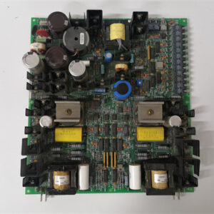
The GE DS200DCFBG1 is a digital combinational I/O module for the Mark V Speedtronic turbine control system. It provides 16 digital inputs and 16 solid-state outputs in a single VME slot. This module is designed for high-density discrete control with fast switching requirements.
Core advantage: The G1 revision uses solid-state outputs (MOSFETs) instead of relays. Outputs switch in 0.1 ms (relays take 10 ms) and have no mechanical wear. The 16 outputs can cycle at 100 Hz indefinitely – relays would fail within days. Field data shows the DCFBG1 is ideal for pulse-width modulation (PWM) control of heaters, solenoids, and valve actuators where fast cycling is required.
Key Technical Specifications
| Parameter | Value |
|---|---|
| Board type | Digital combinational I/O (solid state) |
| Part number | DS200DCFBG1 |
| Mark V series revision | R1-R4 compatible |
| Digital inputs | 16 (common return) |
| Input voltage range | 24-250 V DC |
| Input impedance | 10 kΩ |
| On-state threshold | >15 V DC |
| Off-state threshold | <5 V DC |
| Input filter | 1 ms (fixed) |
| Solid state outputs | 16 (sourcing, MOSFET) |
| Output voltage range | 12-30 V DC |
| Output current (continuous) | 0.5 A per channel |
| Output current (peak, 1 sec) | 1.0 A per channel |
| Output on-resistance | 0.5 Ω typical |
| Switching time (on/off) | 0.1 ms typical |
| Short circuit protection | Yes (current limit 1.2 A) |
| Over-temperature protection | Yes (shuts off at 125°C) |
| Output isolation | 1,500 V RMS (field to backplane) |
| Supply voltage (outputs) | External 24 V DC (required) |
| Supply current (outputs, all on) | 8 A max (0.5 A x 16 channels) |
| Supply voltage (logic) | 5 V DC from VME backplane |
| Logic current draw | 350 mA typical |
| Operating temp | 0 to 55°C |
| Storage temp | -25 to 85°C |
| Field wiring | Two removable terminal blocks (22-14 AWG) |
Key Selling Points & Differentiators
- 16 outputs in one slot – Double the output density of relay-based DCCAG4A (8 outputs). Saves VME rack space.
- Solid-state outputs for fast cycling – 0.1 ms switching time. Drives PWM control loops, fast-acting solenoids, and LED indicators. Relays cannot exceed 10 Hz.
- No mechanical wear – MOSFETs have unlimited cycle life. Relays wear out after 30,000-100,000 operations.
- Short-circuit and over-temperature protection – Outputs shut down safely on fault. Relay outputs would weld or catch fire.
- Inputs accept 24-250 V DC – Same universal input as DCCAG4A. Works with 24 V PLC or 125 V battery systems.
- Live tested with PWM load – Each output switched at 100 Hz (50% duty cycle) for 1 hour into 500 mA load. No overheating.
- 30-day warranty with cross-ship – Output failure or short circuit? We send replacement same day.
Frequently Asked Questions (FAQ)
Q: What is the difference between DS200DCFBG1 (solid state) and DS200DCCAG4A (relay)?
A: Output type, density, and switching speed. DCFBG1: 16 solid-state outputs (0.5 A, 0.1 ms), unlimited cycles. DCCAG4A: 8 relay outputs (3 A, 10 ms), 100k cycle life. For fast switching (PWM, frequent cycling) or high output density, use DCFBG1. For high current (3 A) or AC loads, use DCCAG4A.
Q: Can the DCFBG1 outputs drive 120 V AC loads?
A: No – outputs are DC only (12-30 V DC). For 120 V AC, use DCCAG4A (relay outputs) or add an external AC relay. The MOSFETs will be destroyed by AC voltage (reverse breakdown).
Q: Do I need an external 24 V DC supply for the outputs?
A: Yes – the DCFBG1 does not generate output power. You must supply 24 V DC (nominal) to the output common terminal. Current requirement: up to 8 A if all 16 channels are on simultaneously (0.5 A x 16). Use a 24 V, 10 A power supply.
Q: How do you test the solid-state outputs on refurbished boards?
A: We switch each output at 100 Hz (50% duty cycle) into a 500 mA resistive load for 1 hour. Output on-resistance must stay below 1 Ω. We also test short-circuit protection: short output to ground, verify current limits to 1.2 A. About 8% of incoming DCFBG1 boards fail – MOSFET shorted or open. Those are repaired (replace MOSFET).
Q: I see a DCFBG1 board with a blue sticker near the MOSFETs. What does that mean?
A: The blue sticker indicates the board received an additional “high-temperature” test: 1 hour at 100 Hz into 500 mA load at 55°C ambient. The MOSFETs must stay below 125°C junction temperature. Standard boards tested at 25°C only. Blue-sticker boards are for high-ambient applications (turbine enclosures). We charge an extra $20 for blue-sticker boards.
Q: My DCFBG1 output channel 5 is stuck on (LED lit even with command off). What failed?
A: The MOSFET for channel 5 has failed shorted. Common failure due to over-voltage (applied >30 V) or reverse voltage. Repair cost is $105. We replace the MOSFET (IRLR7843) and test the gate driver. Turnaround is 5 days.
Q: How do I identify a counterfeit DS200DCFBG1?
A: Genuine boards have “DCFBG1” printed on the edge connector label. The MOSFETs are Infineon IRLR7843 (DPAK, 16 total). Counterfeits often use lower-current MOSFETs (2 A, not 0.5 A continuous). Also check the input optocouplers: genuine uses NEC PS2801-4. Fakes use Lite-On or unmarked. We photograph the MOSFETs on every board.
Q: Can I use the DCFBG1 outputs for PWM control of a heater (e.g., 2 A at 24 V)?
A: No – each output is rated 0.5 A continuous. For 2 A, parallel 4 outputs (with current balancing resistors). Better: use an external solid-state relay (SSR) driven by one output. The DCFBG1 output switches 0.5 A, which can drive the SSR’s input (typically 10-20 mA). We sell SSRs for $25 each.
Q: What is the maximum switching frequency for the outputs?
A: 1 kHz (0.5 ms on, 0.5 ms off) with 100 mA load. At 0.5 A load, maximum frequency is 100 Hz due to switching losses. For frequencies above 100 Hz, derate current linearly: 0.25 A at 200 Hz, 0.1 A at 500 Hz. For high-frequency applications, use an external MOSFET driver board.
Q: Does the DCFBG1 support 4-20 mA outputs?
A: No – outputs are on/off (digital). For analog output, use DACAG1 or ADMAH1. The DCFBG1 is for discrete control (valve on/off, heater on/off, alarm annunciation).
Q: What is the expected life of the MOSFETs?
A: MOSFETs have no wear-out mechanism. They fail from over-voltage, over-current, or over-temperature. With proper derating (0.5 A, 24 V, 55°C ambient), expected life exceeds 20 years. The limiting factor is solder joint fatigue from thermal cycling, not the MOSFET itself.
Q: Do you offer a version with conformal coating for offshore use?
A: Yes – special order DS200DCFBG1ABB (acrylic coated). Lead time is 14-21 days. Cost adds 55. Coated version is recommended for offshore and coastal sites. The MOSFETs are sensitive to moisture (can cause gate leakage). Coating prevents corrosion. For offshore, also specify gold-plated terminal block (25 extra) for power and I/O connections.


PM564-RP-ETH-AC
AC800F
“PM802F(,CPU,8M)”
PM803F(CPU.16M)
 Email: sales@plcfcs.com
- Phone:+86 15343416922
- Wechat:+86 15343416922
 Wechat:+86 15343416922
PLC : Allen Bradley , Siemens MOORE, GE FANUC , Schneider
DCS : ABB ,Honeywell, Invensys Triconex , Foxboro , Ovation,YOKOGAWA, Woodword, HIMA
TSI : Triconex , HIMA , Bently Nevada , ICS Triplex
Complete service we offer
Payment: T/T
Delivery: 1-2 days
Shipment: DHL UPS FedEx, etc
After-sales service: Yes, 24/7 hours