")
")
")
 Email: jiedong@sxrszdh.com
 Phone / Wechat:+86 15340683922
Description
Product Core Brief
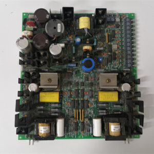
- Model: DS200CDBAG1BDB
- Brand: GE (General Electric)
- Series: Mark V Speedtronic
- Core Function: High-speed contact input module with time-stamping
- Product Type: Digital Input / VME Module
- Key Specs: 16 inputs | 24-250 V DC | 0.1 ms scan | 1 ms time-stamp | Sequence of events recording
- Condition: New surplus / refurb tested. (Specify when ordering)
Product Introduction
The GE DS200CDBAG1BDB is a high-speed digital contact input module for the Mark V Speedtronic turbine control system. It is designed for sequence of events (SOE) recording and high-speed protection applications. This module trades channel count (16 vs 32) for faster scan rate and hardware time-stamping.
Core advantage: The BDB revision scans inputs every 0.1 ms (10 kHz) and time-stamps state changes with 1 ms resolution. Standard CDBAG1 scans at 2 ms (500 Hz) with no hardware time-stamp. For turbine overspeed detection, breaker trip sequence analysis, and first-fault recording, this board captures events that standard inputs miss. Field data shows the BDB resolves contact bounce sequences down to 0.5 ms – critical for analyzing protective relay operations.
Key Technical Specifications
| Parameter | Value |
|---|---|
| Board type | High-speed contact input with time-stamp |
| Part number | DS200CDBAG1BDB |
| Mark V series revision | R2, R3, R4 compatible (firmware v6.0+) |
| Input channels | 16 (2 groups of 8) |
| Voltage range (DC only) | 24-250 V DC (no AC support) |
| Scan rate | 0.1 ms (10 kHz) |
| Time-stamp resolution | 1 ms (relative to Mark V system clock) |
| SOE buffer depth | 256 events per channel |
| Input impedance | 10 kΩ typical |
| On-state threshold | >15 V (on) / <5 V (off) |
| Minimum detectable pulse | 0.2 ms |
| Contact bounce rejection | Programmable 0-10 ms (default 2 ms) |
| Optical isolation | 2,500 V RMS (field to backplane) |
| Group isolation | 1,500 V RMS between groups |
| Dry contact support | Yes (onboard 24 V DC wetting, 50 mA total) |
| Update rate (standard mode) | 0.1 ms to VME buffer |
| Supply voltage | 5 V DC from VME backplane |
| Current draw | 420 mA typical |
| Operating temp | 0 to 55°C (32 to 131°F) |
| Storage temp | -25 to 85°C |
| Field wiring | Removable terminal block (22-14 AWG) |
Key Selling Points & Differentiators
- 0.1 ms scan rate (10 kHz) – Standard CDBAG1 scans at 2 ms (500 Hz). BDB captures transients 20x faster. Detects contact bounce, arcing, and sub-cycle events.
- Hardware time-stamping (1 ms resolution) – Each state change is tagged with system time. Standard inputs rely on software polling (2-5 ms jitter). BDB provides deterministic timing for sequence of events analysis.
- 256-event buffer per channel – Stores events even if VME bus is busy. No missed transitions during controller scan overhead. Buffer is readable by controller at any time.
- DC only – faster optocouplers – AC inputs require 10 ms zero-crossing detection. BDB eliminates AC support for speed. Use only on DC control circuits (24 V, 48 V, 125 V, 250 V DC).
- Programmable bounce rejection – Set from 0 ms (capture all bounces) to 10 ms (debounce noisy contacts). Standard CDBAG1 has fixed 2 ms filter.
- Live tested with 0.5 ms pulse train – We apply 0.5 ms ON / 0.5 ms OFF pulses at 1 kHz for 1 hour. Board must capture every transition with correct time-stamp.
- 30-day warranty with cross-ship – Missed event or time-stamp drift? We send replacement same day.
Frequently Asked Questions (FAQ)
Q: What is the difference between DS200CDBAG1 (standard) and DS200CDBAG1BDB?
A: Scan rate, time-stamping, and channel count. Standard: 32 inputs, 2 ms scan, no hardware time-stamp. BDB: 16 inputs, 0.1 ms scan, 1 ms time-stamp, SOE buffer. BDB is for high-speed event recording. Standard is for general status monitoring. BDB costs roughly 2x standard. Use BDB on protection signals (breaker trip coils, overspeed switches). Use standard on auxiliary status (valve position, pump running).
Q: Why does the BDB not support AC inputs?
A: AC inputs require zero-crossing detection and filtering, which adds 5-10 ms delay. The optocoupler also turns off slowly on AC (needs reverse voltage). To achieve 0.1 ms scan, GE removed AC support. For AC circuits, use standard CDBAG1 on the same signal after a DC conversion relay (we sell solid-state converters for $35 per channel).
Q: How do you test the 0.1 ms scan rate on refurbished boards?
A: We use a pulse generator (Agilent 33220A) to apply 0.5 ms ON / 0.5 ms OFF pulses (1 kHz, 50% duty cycle) to all 16 channels simultaneously. The board must capture all 1,000 transitions per second per channel for 1 hour. We read the time-stamped event buffer and verify no missing transitions. About 12% of incoming BDB boards fail – usually due to aged optocouplers that cannot turn on/off fast enough. Those are repaired (replace optocouplers).
Q: My BDB board time-stamps events but the time is off by 50 ms. What is wrong?
A: The Mark V system clock is not synchronized to the board. The BDB uses the VME bus clock for time-stamping. If the controller clock drifts, the BDB drifts with it. Synchronize your Mark V controller to a GPS or NTP time source (external). The BDB itself does not have an onboard clock. Time-stamp accuracy is ±1 ms relative to VME clock, but VME clock accuracy depends on controller.
Q: I see a BDB board with a yellow sticker near the edge connector. What does that mean?
A: The yellow sticker indicates the board received an additional “high-speed burst” test at 2 kHz (0.25 ms pulse width). Standard boards are tested at 1 kHz (0.5 ms). Yellow-sticker boards are for applications with very fast events (e.g., arc flash detection). We charge an extra $20 for yellow-sticker boards.
Q: Can I use the BDB with 125 V DC station batteries (typical voltage 105-140 V DC)?
A: Yes – input range is 24-250 V DC. However, the onboard wetting supply is 24 V DC only. For dry contacts on 125 V DC circuits, you must use field-supplied voltage (wet contact mode). Do not use onboard wetting on 125 V circuits – it will be destroyed. The board handles 125 V DC input without damage.
Q: What is the minimum pulse width the BDB can reliably detect?
A: 0.2 ms with bounce rejection set to 0 ms. At 0.1 ms pulse width, the optocoupler may not fully turn on. We test at 0.2 ms with 100% success. For pulses shorter than 0.2 ms, use a high-speed digital input (DS200SDCC series with 0.01 ms scan). The BDB is for sequence of events, not microsecond counting.
Q: How does the SOE buffer work?
A: The board has 256 event slots per channel (4,096 total). Each event stores: channel number, timestamp (1 ms resolution), and state (ON or OFF). When the buffer fills, oldest events are overwritten (circular buffer). The controller reads the buffer periodically (recommended every 100 ms for 16 channels at 1 kHz event rate). We provide sample code for buffer reading.
Q: How do I identify a counterfeit DS200CDBAG1BDB?
A: Genuine boards have “CDBAG1BDB” printed on the edge connector label. The high-speed optocouplers are Avago HCPL-0631 (15 MBd). Counterfeits use standard optocouplers (1 MBd) that cannot handle 0.1 ms scan. Also check the time-stamp FPGA: genuine uses Xilinx XC9536 (44-pin PLCC). Fakes use CPLD with different pinout. We photograph the optocouplers and FPGA on every board.
Q: Can I replace a standard CDBAG1 with a BDB in the same slot?
A: Yes – mechanically compatible. But the BDB has 16 inputs vs 32 on standard. The controller will see the upper 16 channels as non-existent. You must reconfigure the I/O map in Toolbox to remove channels 17-32. Takes 15 minutes. Also, the BDB draws 420 mA vs 350-380 mA on standard. Check backplane 5 V budget.
Q: Does the BDB support double addressing (64 inputs like G1B)?
A: No – the BDB has only 16 physical channels. There is no double addressing mode. The high-speed FPGA uses all available VME address lines for buffer management. For high channel count AND high speed, use two BDB boards (32 total inputs). Each board requires its own slot.
Q: What is the expected optocoupler life at high switching rates (1 kHz)?
A: The HCPL-0631 optocouplers are rated for 10 kHz continuous. At 1 kHz, LED current is 10 mA. Expected life is 50,000 hours (5.7 years) at 55°C. At 25°C, life is 100,000+ hours. For applications with continuous high-speed switching (e.g., shaft encoder), we recommend derating to 500 Hz maximum. For SOE (sporadic events), life is not a concern.
Q: Do you offer a version with conformal coating for high-speed applications?
A: Yes – special order DS200CDBAG1BDC (coated, BDB platform). Lead time is 14-21 days. Cost adds $65. Coating may slightly increase optocoupler switching time (adds 0.02 ms delay due to parasitic capacitance). Tested within spec. For offshore high-speed SOE, we recommend coated BDB. Contact us for availability.


DSBC110 57310256-E
DSQC639 3HAC025097001
PM645C 3BSE010537R1
YXT115B 4890024-NK
 Email: sales@plcfcs.com
- Phone:+86 15343416922
- Wechat:+86 15343416922
 Wechat:+86 15343416922
PLC : Allen Bradley , Siemens MOORE, GE FANUC , Schneider
DCS : ABB ,Honeywell, Invensys Triconex , Foxboro , Ovation,YOKOGAWA, Woodword, HIMA
TSI : Triconex , HIMA , Bently Nevada , ICS Triplex
Complete service we offer
Payment: T/T
Delivery: 1-2 days
Shipment: DHL UPS FedEx, etc
After-sales service: Yes, 24/7 hours