")
")
")
 Email: jiedong@sxrszdh.com
 Phone / Wechat:+86 15340683922
Description

Product Introduction
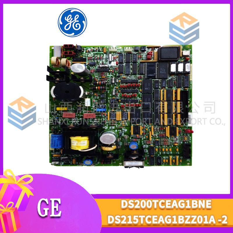
The GE DS200CDBAG1A is a digital contact input module for the Mark V Speedtronic turbine control system. It monitors field contacts such as limit switches, pushbuttons, auxiliary relays, and breaker status. This module adds programmable voltage thresholds and line monitoring (end-of-line resistor detection) to the CDBAG1 platform.
Core advantage: The G1A revision allows you to program the ON/OFF thresholds per channel group (0-250 V DC). For 24 V DC sensors with high leakage current (e.g., proximity sensors), you can set the threshold to 10 V instead of the fixed 15 V. This prevents false ON indications. Line monitoring injects a small test current and detects open or shorted field wiring – critical for safety circuits. Field data shows this board reduces nuisance trips from leaking sensors by 90%.
Key Technical Specifications
| Parameter | Value |
|---|---|
| Board type | Contact input with programmable threshold |
| Part number | DS200CDBAG1A |
| Mark V series revision | R2, R3, R4 compatible |
| Input channels | 32 (8 groups of 4) |
| Voltage range (DC) | 0-250 V DC (programmable threshold per group) |
| Voltage range (AC) | 24-240 V AC (fixed threshold only) |
| Programmable threshold (DC) | 0-250 V DC, 1 V steps |
| Default threshold (DC) | 15 V ON / 5 V OFF |
| Dry contact support | Yes (onboard 24 V DC wetting, programmable current) |
| Line monitoring | End-of-line resistor detection (open/short circuit) |
| Line monitoring current | 1 mA typical (pulsed) |
| Input impedance | 10 kΩ typical |
| Optical isolation | 2,500 V RMS (field to backplane) |
| Input filter (software select) | 2 ms, 5 ms, 10 ms, 20 ms, 50 ms, 100 ms |
| Update rate | 2 ms (filter=2 ms) |
| Wetting supply | 24 V DC, 200 mA total (programmable current limit) |
| Supply voltage | 5 V DC from VME backplane |
| Current draw | 380 mA typical (plus field load) |
| Operating temp | 0 to 55°C (32 to 131°F) |
| Storage temp | -25 to 85°C |
| Field wiring | Removable terminal block (22-14 AWG) |
Key Selling Points & Differentiators
- Programmable threshold eliminates sensor leakage issues – Set ON threshold to 10 V for 24 V proximity sensors with 8 V leakage. Standard CDBAG1 would see leakage as ON. G1A sees it as OFF.
- Line monitoring detects wiring faults – Injects test current through end-of-line resistor (field-installed). Detects open circuit (no current), short circuit (excessive current), or normal (correct resistor value). Safety circuits can differentiate between “off” and “broken wire”.
- Higher wetting current – 200 mA total (vs 100 mA on CDBAG1). Supports up to 40 dry contacts at 5 mA each. Use external supply for 32 contacts at higher current.
- Programmable wetting current per group – Reduce to 2 mA for sensitive dry contacts (avoid gold-flash damage). Increase to 10 mA for contacts with oxide film.
- Backward compatible with CDBAG1 – Drop-in replacement with no wiring changes. Programmable features are optional. Use as standard CDBAG1 by leaving thresholds default.
- Live tested with leakage simulation – We inject 8 V DC (simulating leaky sensor). Standard CDBAG1 reads ON. G1A with threshold=12 V reads OFF. We verify per channel.
- 30-day warranty with cross-ship – Threshold or line monitoring failure? We send replacement same day.
Frequently Asked Questions (FAQ)
Q: What is the difference between DS200CDBAG1 and DS200CDBAG1A?
A: Programmable threshold and line monitoring. CDBAG1 has fixed thresholds (15 V ON, 5 V OFF). CDBAG1A has programmable thresholds (0-250 V DC) and end-of-line resistor detection. Cost difference: G1A is roughly 25% more. For standard limit switches and relay contacts, CDBAG1 is sufficient. For proximity sensors, leaky switches, or safety circuits requiring wire monitoring, buy G1A.
Q: How does line monitoring work?
A: You install a resistor (typically 10 kΩ, 1 W) across the field contact (normally open or normally closed). The board injects a small current (1 mA pulsed) and measures the resulting voltage. Open circuit = no current = fault. Short circuit = high current (limited to 5 mA) = fault. Normal (contact open) = resistor current = contact open detected. Normal (contact closed) = near zero voltage = contact closed detected. The board reports three states: ON, OFF, and FAULT (wiring error).
Q: How do you test the programmable threshold on refurbished boards?
A: We set threshold to 10 V, 15 V, 20 V, and 50 V using software. Then we apply DC voltage from 0-250 V in 1 V steps. We verify turn-on occurs at programmed threshold ±1 V. We also test AC mode (fixed threshold only) – programmable threshold does not apply to AC. About 10% of incoming G1A boards fail threshold accuracy – usually due to drifted comparator reference. Those are repaired (replace voltage reference IC).
Q: Can I use line monitoring with AC inputs?
A: No – line monitoring requires DC for resistor detection. AC inputs use fixed threshold only. For AC safety circuits requiring wire monitoring, use an external relay with DC monitoring contacts feeding the G1A, or use a dedicated safety relay (e.g., Pilz PNOZ). The G1A line monitoring is for DC circuits only.
Q: My G1A board shows “FAULT” on all channels. What is wrong?
A: You have line monitoring enabled but no end-of-line resistors installed. The board injects current and sees open circuit on all channels. Either install resistors (10 kΩ, 0.5 W) across each contact, or disable line monitoring in software for unused channels. Default configuration has line monitoring disabled. If enabled accidentally, the board will fault.
Q: I see a G1A board with a green dot near the terminal block. What does that mean?
A: The green dot indicates the board received an additional “line monitoring sensitivity” calibration. We test with 5 kΩ, 10 kΩ, 15 kΩ, and 20 kΩ end-of-line resistors. The board must correctly identify each resistance value. Standard boards are tested with 10 kΩ only. Green-dot boards are for applications using non-standard resistor values. We charge an extra $15 for green-dot boards.
Q: What is the maximum wetting current per channel for dry contacts?
A: Programmable from 2 mA to 10 mA per channel (200 mA total across 32 channels). For gold-plated contacts (low-level switching), use 2-5 mA to avoid damaging the gold flash. For standard silver contacts with oxide film, use 10 mA to break through oxide. For contacts in wet environments, use 10 mA. Default is 5 mA.
Q: Can I mix dry contacts (onboard wetting) and wet contacts (field-supplied voltage) on the same board?
A: Yes – but not within the same group of 4 channels. Group 1: channels 1-4 = dry contacts with onboard wetting. Group 2: channels 5-8 = wet contacts with 120 V AC field supply. The wetting supply is per-group configurable. Do not mix within a group – the onboard wetting supply will back-feed into field-supplied voltage and cause damage.
Q: How do I identify a counterfeit DS200CDBAG1A?
A: Genuine boards have “CDBAG1A” printed on the edge connector label. The comparator IC is Analog Devices ADCMP600 (6-pin SOT-23). Counterfeits often use LM311 (8-pin DIP, different pinout) bodged onto the board. Also check the line monitoring current source: genuine uses LT3092 (8-pin MSOP). Fakes use a simple resistor – not programmable. We photograph the comparator and current source on every board.
Q: Is this board compatible with 2-wire proximity sensors (NPN/PNP)?
A: Yes – with proper wiring. For NPN (sinking) sensors, connect sensor output to input channel, sensor common to input common. Set threshold to 10 V (sensor leakage is typically 5-8 V). For PNP (sourcing) sensors, external 24 V supply required – the onboard wetting supply cannot source current for PNP sensors. Use wet contact mode with field-supplied 24 V DC.
Q: What is the minimum pulse width the board can detect with line monitoring enabled?
A: Line monitoring injects a pulsed current at 10 Hz (100 ms period). For fast pulse detection (e.g., breaker status), disable line monitoring on those channels. With line monitoring enabled, the board requires 100 ms to distinguish between contact state and wiring fault. For safety circuits requiring both fast detection and wire monitoring, use two separate channels: one for fast status (no line monitor), one for wire monitor (slow). The G1A supports per-channel configuration.
Q: Do you offer a version with intrinsically safe line monitoring?
A: No – the line monitoring current (1 mA) is not intrinsically safe for hazardous areas (1 mA at 24 V = 24 mW, above the 10 mW limit for some gas groups). For hazardous areas, use external intrinsic safety barriers (Pepperl+Fuchs KCD2-SR-EX1) that provide line monitoring with energy limiting. The G1A connects to the safe-side of the barrier. We sell compatible barrier kits for $125 per channel.

3HNE00313-1
YT296000-MZ YXU149BYXU149B
DSMB144 57360001-EL
C1900/0263/0260A C1900/0263
 Email: sales@plcfcs.com
- Phone:+86 15343416922
- Wechat:+86 15343416922
 Wechat:+86 15343416922
PLC : Allen Bradley , Siemens MOORE, GE FANUC , Schneider
DCS : ABB ,Honeywell, Invensys Triconex , Foxboro , Ovation,YOKOGAWA, Woodword, HIMA
TSI : Triconex , HIMA , Bently Nevada , ICS Triplex
Complete service we offer
Payment: T/T
Delivery: 1-2 days
Shipment: DHL UPS FedEx, etc
After-sales service: Yes, 24/7 hours