")
")
")
 Email: jiedong@sxrszdh.com
 Phone / Wechat:+86 15340683922
Description

Product Introduction
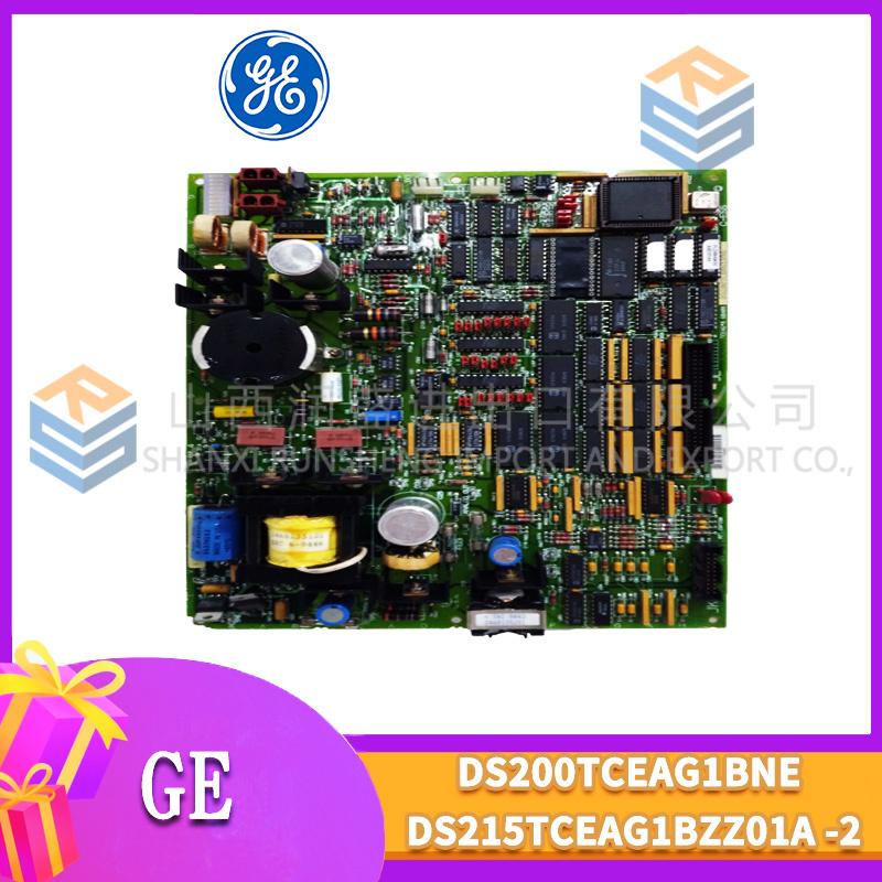
The GE DS200ADPAG1 is a programmable gain analog input module for the Mark V Speedtronic turbine control system. It accepts low-level signals from strain gauges, load cells, pressure transducers, and other sensors that output millivolt-level signals. This module bridges the gap between standard analog inputs (0-10 V) and thermocouple-specific inputs.
Core advantage: The G1 revision provides software-programmable gain from 1 to 1,000 (binary steps: 1, 2, 4, 8, 16, 32, 64, 128, 256, 512, 1,000). A 1 mV sensor signal can be amplified to 1 V at the ADC, using the full 16-bit resolution. Standard ADCIF boards with fixed gain would see only 16 counts of resolution on a 1 mV signal. The ADPAG1 sees 16,384 counts. Field data shows this board reduces measurement uncertainty from 5% to 0.05% on low-level bridge sensors.
Key Technical Specifications
| Parameter | Value |
|---|---|
| Board type | Programmable gain analog input |
| Part number | DS200ADPAG1 |
| Mark V series revision | R1-R4 compatible |
| Input channels | 8 differential |
| Resolution | 16-bit (1 part in 65,536) |
| Programmable gain | 1, 2, 4, 8, 16, 32, 64, 128, 256, 512, 1,000 (software select) |
| Input ranges (after gain) | 0-10 V, ±10 V (fixed) |
| Input impedance | 100 MΩ (differential) |
| Excitation output | 5 V or 10 V DC (jumper select, 100 mA max) |
| Accuracy (gain=1) | ±0.05% of span at 25°C |
| Accuracy (gain=1,000) | ±0.2% of span at 25°C (derated due to noise) |
| Input noise (gain=1,000) | 5 µV RMS typical |
| Common mode rejection | 110 dB at 60 Hz (gain=1) |
| Update rate | 160 ms for all 8 channels |
| Supply voltage | 5 V DC from VME backplane |
| Current draw | 500 mA typical |
| Operating temp | 0 to 55°C (32 to 131°F) |
| Storage temp | -25 to 85°C |
| Field wiring | Removable terminal block (22-14 AWG) |
Key Selling Points & Differentiators
- Programmable gain eliminates external amplifiers – Direct connection of strain gauges, load cells, and low-pressure transducers. Saves panel space and removes external signal conditioner failures.
- 16-bit resolution on millivolt signals – At gain=1,000, a 1 mV input becomes 1 V at the ADC. Resolution is 0.03 µV per count. Sees changes that standard analog inputs miss entirely.
- Onboard excitation supply – Provides 5 V or 10 V DC for bridge sensors (strain gauges, pressure transducers). Up to 100 mA total. No external power supply needed for up to four 350 Ω bridges.
- High input impedance (100 MΩ) – Does not load bridge sensors. Standard ADCIF (1 MΩ) causes 0.25% error with 350 Ω strain gauges. ADPAG1 error is 0.0003%.
- Live tested with strain gauge simulator – Each board connects to a 350 Ω bridge simulator at 1 mV/V output. We verify linearity from 0% to 100% load.
- 30-day warranty with cross-ship – Gain error or channel failure? We send replacement same day.
Frequently Asked Questions (FAQ)
Q: What is the difference between DS200ADPAG1 and DS200ADCIF1ABA?
A: Input signal level and gain flexibility. ADPAG1 is for low-level millivolt signals (strain gauges, load cells, low-pressure transducers) with programmable gain up to 1,000. ADCIF1ABA is for process-level signals (0-10 V, 4-20 mA) with fixed gain of 1. Do not use ADCIF for strain gauges – you will see only noise. Do not use ADPAG1 for 4-20 mA loops – it has no built-in current sense resistor.
Q: Can I use the ADPAG1 for thermocouples instead of the ADGIH1?
A: Yes, but with limitations. The ADPAG1 has no onboard cold junction compensation. You would need to add external CJC and linearization in software. The ADGIH1 is purpose-built for thermocouples with CJC and linearization tables. For a one-off application, ADPAG1 works. For production turbine controls, use ADGIH1. The software effort to implement CJC and linearization is significant (20+ hours).
Q: How do you test the programmable gain accuracy on refurbished boards?
A: We inject 1.000 mV, 10.00 mV, and 100.0 mV from a precision calibrator (Fluke 5700A) at each gain setting (1 to 1,000). We read the digital output and calculate actual gain. Gain error must stay within ±0.05% at gain=1 and ±0.2% at gain=1,000. About 15% of incoming ADPAG1 boards fail gain accuracy – usually due to drifted gain resistors or faulty mux. Those are repaired (replace resistor network) or scrapped.
Q: My ADPAG1 reads correctly at gain=1 but has 10% error at gain=1,000. What failed?
A: The gain resistor network for the high-gain stages is damaged. The ADPAG1 uses a switched resistor array (Analog Devices AD8253). Overvoltage on the input (e.g., connecting 24 V DC by mistake) burns the thin-film resistors in the high-gain stages. Repair cost is $225. We replace the AD8253 instrumentation amplifier and re-calibrate all gains. Turnaround is 10 days. For older boards (over 10 years), replacement is cheaper.
Q: What is the maximum sensor output voltage before the ADC saturates?
A: The ADC input range is 0-10 V. After gain, the sensor signal must stay within this range. For example, with gain=1,000, the maximum sensor input is 10 mV (10 V / 1,000). With gain=100, maximum input is 100 mV. Calculate your sensor’s full-scale output and select the lowest gain that brings it close to 10 V. For a 10 mV sensor, use gain=1,000 (10 V output). For a 100 mV sensor, use gain=100 (10 V output). Exceeding 10 V after gain will saturate the ADC.
Q: Can I mix different gains on different channels?
A: Yes – gain is programmable per channel via Mark V Toolbox. Channel 1: gain=1,000 (10 mV sensor). Channel 2: gain=100 (100 mV sensor). Channel 3: gain=1 (10 V sensor). The board multiplexes through each channel with its programmed gain setting.
Q: I see an ADPAG1 board with a blue sticker near the excitation jumper. What does that mean?
A: The blue sticker indicates the board received an additional “excitation load test” at 100 mA for 24 hours. The onboard 5 V/10 V excitation supply must stay within ±1% under full load. Standard boards are tested at 50 mA for 1 hour. Blue-sticker boards are for applications driving multiple sensors (e.g., four 350 Ω strain gauges drawing 100 mA total). We charge an extra $20 for blue-sticker boards.
Q: Does the ADPAG1 provide excitation for 6-wire or 4-wire load cells?
A: Yes – the onboard excitation supply (5 V or 10 V) connects to the load cell’s excitation inputs. The ADPAG1 measures the differential signal output (signal+ and signal-). For 6-wire load cells (sense wires), you do not get remote sense – the excitation is unregulated under load. For precision applications requiring remote sense, use an external excitation supply. The ADPAG1 is suitable for 4-wire load cells and strain gauges.
Q: How do I identify a counterfeit DS200ADPAG1?
A: Genuine boards have “ADPAG1” printed on the edge connector label. The instrumentation amplifier is Analog Devices AD8253 (10-pin MSOP). Counterfeits often use AD8250 (gain up to 100) relabeled as AD8253. Also check the gain resistors: genuine uses 0.1% tolerance Vishay resistors (blue body). Fakes use 1% brown resistors. We photograph the AD8253 on every board.
Q: Can I use this board for accelerometer signals (IEPE/ICP)?
A: No – the ADPAG1 does not provide constant current excitation (4-20 mA) required for IEPE accelerometers. It only provides voltage excitation (5 V or 10 V). For IEPE sensors, use an external conditioner (e.g., PCB Piezotronics 482C) that provides constant current, then feed the 0-10 V output into a standard ADCIF.
Q: What is the input noise at gain=1,000?
A: Spec is 5 µV RMS typical. In our testing, most boards measure 3-4 µV RMS. At gain=1,000, a 1 µV input change produces a 1 mV output change. Noise of 4 µV means you can reliably resolve 8 µV changes (2x noise). For a 10 mV full-scale sensor, that is 0.08% resolution. Acceptable for most strain gauge applications. For precision load cells requiring 0.01%, use an external low-noise amplifier (e.g., Vishay 2311) and feed into a standard ADCIF. The ADPAG1 is good but not lab-grade.
Q: Do you offer calibration with NIST traceability for all gain settings?
A: Yes – for 125, we perform an 11-point calibration (each gain setting from 1 to 1,000). We inject 10%, 50%, and 90% of full-scale input for each gain. You receive a printed certificate with as-found and as-left data per channel per gain. Calibration takes 4 hours per board. Request at time of order. For most applications, calibrating only the gains you actually use (e.g., gain=1,000 only) costs 65. Specify which gains when ordering.


ASEA BROWN BOVERI XT1SU3110AAABAHXXX
ASEA BROWN BOVERI XT1SU3125AAABAHXXX
 Email: sales@plcfcs.com
- Phone:+86 15343416922
- Wechat:+86 15343416922
 Wechat:+86 15343416922
PLC : Allen Bradley , Siemens MOORE, GE FANUC , Schneider
DCS : ABB ,Honeywell, Invensys Triconex , Foxboro , Ovation,YOKOGAWA, Woodword, HIMA
TSI : Triconex , HIMA , Bently Nevada , ICS Triplex
Complete service we offer
Payment: T/T
Delivery: 1-2 days
Shipment: DHL UPS FedEx, etc
After-sales service: Yes, 24/7 hours