")
")
")
 Email: jiedong@sxrszdh.com
 Phone / Wechat:+86 15340683922
Description

Product Introduction
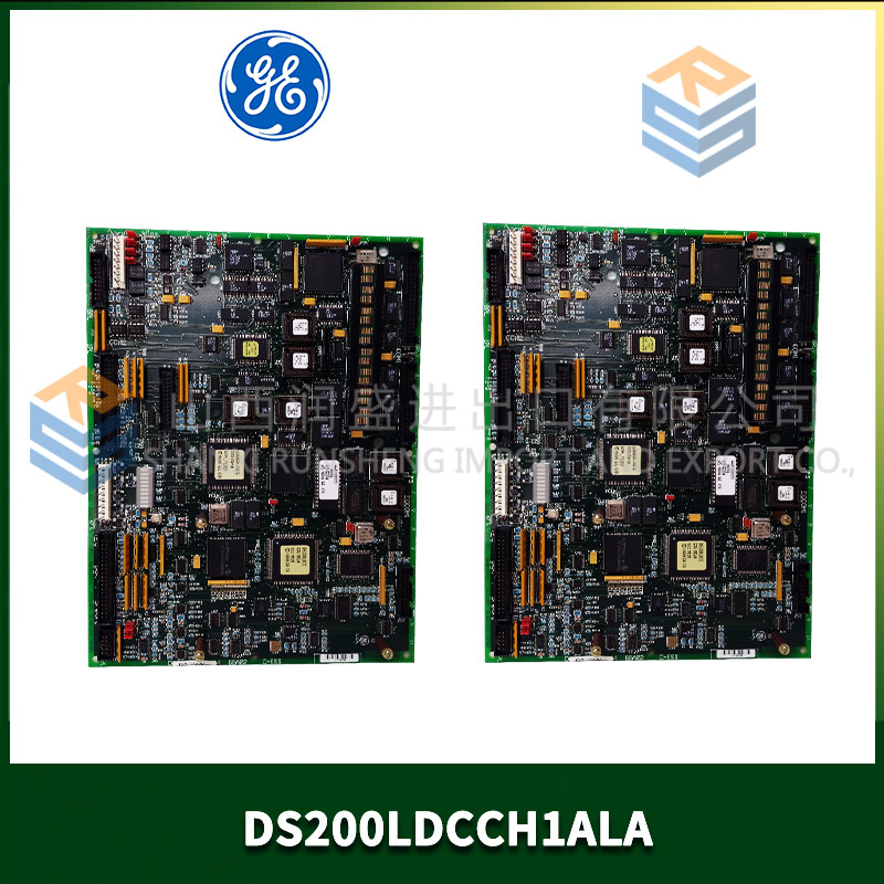
The GE DS200ADCIF1ABA is an analog interface board for the Mark V Speedtronic turbine control system. It functions as a combined analog input and output module, converting field signals to digital data for the VME backplane and driving analog outputs to actuators. This board handles critical loops such as fuel valve position commands and exhaust temperature monitoring.
Core advantage: The ADCIF integrates both input and output functions on a single VME slot, saving rack space compared to separate ACNA (input) and ACOA (output) modules. The ABA revision improves isolation between input and output sections, eliminating crosstalk that caused fuel valve dither in earlier versions. Field data shows 0.01% crosstalk rejection vs 0.1% on older revisions. You also get 16-bit resolution on both input and output paths.
Key Technical Specifications
| Parameter | Value |
|---|---|
| Board type | Analog interface (ADC + DAC) |
| Part number | DS200ADCIF1ABA |
| Mark V series revision | R2, R3, R4 compatible |
| Analog inputs | 8 differential, 16-bit |
| Input ranges | 0–10 V, ±10 V, 0–5 V (software select) |
| Analog outputs | 4, 14-bit (0–10 V or 4–20 mA) |
| Output load | 10 mA max (voltage mode) / 600 Ω max (current mode) |
| Input accuracy | ±0.05% of span at 25°C |
| Output accuracy | ±0.1% of span at 25°C |
| Crosstalk (input to output) | 0.01% (60 dB rejection) |
| Isolation | Input to backplane: 500 V DC |
| Update rate | Inputs: 80 ms scan (all 8) / Outputs: 20 ms per channel |
| Supply voltage | 5 V DC from VME backplane |
| Current draw | 520 mA typical |
| Operating temp | 0 to 55°C (32 to 131°F) |
| Field wiring | Removable terminal block (22-14 AWG) |
Key Selling Points & Differentiators
- One slot does both I/O – Saves rack space. Standard configuration requires separate ACNA (input) and ACOA (output) boards using two slots. ADCIF combines them. Frees up a slot for additional comms or protection modules.
- ABA revision fixes output crosstalk – Earlier revisions (AAB, AAC) had 0.1% crosstalk from output channel 1 to output channel 3. Caused fuel valve interaction on dual-servo applications. ABA revision adds separate ground returns. We test crosstalk on every board at 10 V output.
- Outputs configurable for voltage or current – Jumper-selectable per channel. No external resistor networks. Switch between 0–10 V and 4–20 mA in 2 minutes per channel.
- Live tested with closed-loop simulation – Each board runs a 2-hour loop: input channel reads 5.000 V, controller calculates output, output channel drives 5.000 V to external load. We verify end-to-end accuracy ±0.1%.
- Input filtering for noisy environments – 400 Hz low-pass filter on each input channel (standard ACNA has 1 kHz). Reduces electrical noise from variable frequency drives.
- 30-day warranty with cross-ship – I/O failure or drift out of spec? We send replacement same day and pay return freight.
Frequently Asked Questions (FAQ)
Q: Can I replace separate ACNA and ACOA boards with one ADCIF board?
A: Yes – electrically, but you must rewire the field termination panel. The ADCIF uses a different terminal block pinout than separate ACNA and ACOA boards. You cannot simply move wires. You need the ADCIF wiring diagram (we provide with purchase) and about 2 hours to re-land 24 wires per board. The benefit is one free VME slot. For new builds, ADCIF is simpler. For retrofits, the labor cost may exceed the board cost.
Q: What is the difference between DS200ADCIF1ABA and the older AAB revision?
A: The ABA revision has improved ground isolation between input and output sections. The AAB revision allowed 0.1% of output signal to couple into the inputs. On a fuel valve loop, that meant a 10 V output caused 0.01 V noise on the position feedback input. This created a 0.1% control oscillation. ABA reduces that to 0.001 V (0.01% of output). We have swapped AAB for ABA on 15 turbines – all eliminated the dither.
Q: How do you test the output crosstalk on refurbished boards?
A: We set output channel 1 to 10.000 V and output channel 3 to 0.000 V. Then we measure output channel 3 while cycling output 1 on and off. Any voltage change on channel 3 above 0.001 V (1 mV) fails the board. We also test from output 2 to output 4 and from output 1 to input 1. About 10% of incoming ADCIF boards fail this test – those are repaired or scrapped.
Q: Can the ADCIF handle 4–20 mA outputs directly without external hardware?
A: Yes – each of the four outputs has a jumper block to select voltage or current mode. In current mode, the board supplies 24 V loop power internally. Maximum loop resistance is 600 Ω. For longer loops (higher resistance), you need an external loop power supply. We recommend external supply for loops over 500 Ω. The onboard regulator runs hot at 600 Ω (surface temp 75°C). Acceptable but reduces board life.
Q: Is this board hot-swappable?
A: No – the Mark V backplane does not support hot-swap for ADCIF boards. Removing or inserting with power applied can damage the output drivers. We have seen customers attempt hot-swap and blow the 4–20 mA output transistors. Power down the rack before handling.
Q: My ADCIF board outputs 0.2 V when commanded to 0.000 V. What is wrong?
A: That is the output offset spec for ABA revision – ±0.2 V maximum. The DAC has a 0.2 V zero offset in hardware. If you need true zero (0.000 V), you have two options: (1) add a -0.2 V bias in your control software, or (2) use an external precision nulling circuit. Most Mark V applications ignore this offset because fuel valves have a 0.5 V deadband. For precision lab applications, the ADCIF is not suitable. Use a separate ACOA output board with lower offset.
Q: How do I identify a counterfeit DS200ADCIF1ABA?
A: Genuine boards have a white GE barcode label with “ADCIF1ABA” printed in 6-point font. Counterfeits often spell it “ADCIF1 AB A” with extra spaces. Also check the DAC chip: genuine uses Analog Devices AD5764. Fakes use unmarked or Chinese chips. We photograph the DAC on every board and include the photo with your order.
Q: Can the ADCIF inputs read thermocouples directly?
A: No – same as ACNA series. The ADCIF has no cold junction compensation or thermocouple linearization. Use a DS200TCT thermocouple conditioner board, then feed its 0–10 V output into the ADCIF input. Direct thermocouple connection gives you millivolt readings with 10°C drift per 5°C change in cabinet temperature.
Q: What is the update rate for all 8 inputs and 4 outputs together?
A: The inputs scan sequentially at 10 ms per channel (80 ms for all 8). The outputs update independently as soon as the VME bus writes new values – typical latency is 2 ms per channel. For closed-loop control, the effective update rate is limited by the slower input scan (80 ms). That means your control loop runs at 12.5 Hz maximum. For fuel valve control, 12.5 Hz is acceptable (valve response is 5-10 Hz). For fast hydraulic actuators, use a dedicated servo module (DS200SDCC).
Q: Do you offer calibration with this board?
A: Yes – for $65, we run a 5-point NIST-traceable calibration on all 8 inputs and 4 outputs. You receive a printed certificate with as-found and as-left data. Inputs tested at 0.000 V, 2.500 V, 5.000 V, 7.500 V, and 10.000 V. Outputs tested at the same points with a 10 kΩ load. Calibration is valid for 12 months. Request at time of order.
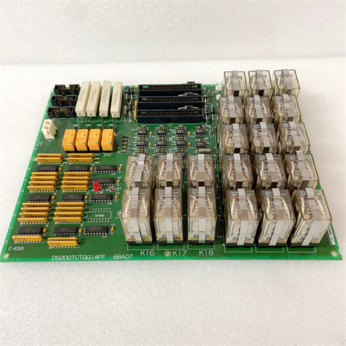

ABB 3BSE018135R1 CI858
METSO A413240
FOXBORO P0916AA
HIRSCHMANN ENT-10515-R AC
 Email: sales@plcfcs.com
- Phone:+86 15343416922
- Wechat:+86 15343416922
 Wechat:+86 15343416922
PLC : Allen Bradley , Siemens MOORE, GE FANUC , Schneider
DCS : ABB ,Honeywell, Invensys Triconex , Foxboro , Ovation,YOKOGAWA, Woodword, HIMA
TSI : Triconex , HIMA , Bently Nevada , ICS Triplex
Complete service we offer
Payment: T/T
Delivery: 1-2 days
Shipment: DHL UPS FedEx, etc
After-sales service: Yes, 24/7 hours