")
")
")
 Email: jiedong@sxrszdh.com
 Phone / Wechat:+86 15340683922
Description
Product Introduction
The I/O rack has power. The field transmitters are dead. You check the PGR-4C-E. One channel is dark. That’s the channel feeding the pressure transmitters.
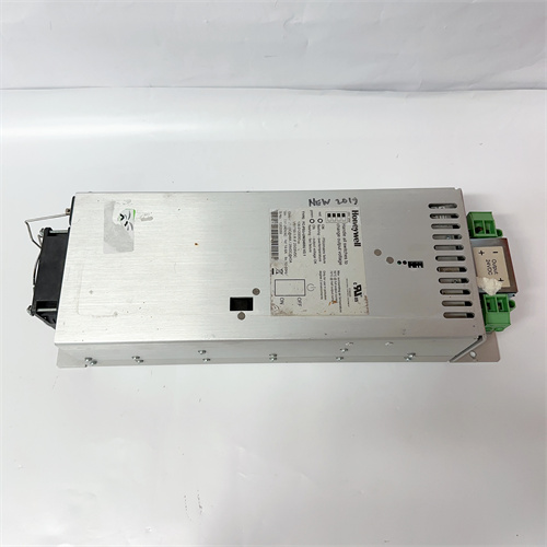
The HONEYWELL PGR-4C-E is the four‑channel power supply for the TDC 3000 I/O racks. It takes 120 or 240 VAC and gives you four independent 24 VDC outputs. Each channel has its own fuse, its own regulator, its own LED. If one channel shorts, the other three keep running. That’s the whole point of this design—you don’t lose the whole rack when one loop dies.
I’ve pulled these out of refineries where they’d been running since the early 1990s. The caps dry out. The regulators drift. The fuses blow. One plant had a PGR-4C-E that was putting out 21 VDC on channel 2—the analog inputs were reading low, but nobody caught it until the batch recipe failed. The fix was swapping the supply. The other three channels were still in spec. That’s the beauty of four independent outputs. You don’t have to replace the whole unit when one channel goes soft.
Key Technical Specifications
| Parameter | Value |
|---|---|
| Input Voltage | 120/240 VAC ±10%, 47–63 Hz, selectable |
| Outputs | 4 independent, 24 VDC each |
| Output Current | 1.5 A per channel maximum |
| Total Output | 6 A maximum (across all 4 channels) |
| Regulation | ±5% over full load range |
| Ripple | <100 mV p-p per channel |
| Protection | Each channel: fuse, overcurrent, short circuit |
| LEDs | Per‑channel OK, input power OK |
| Operating Temp | 0 to +50 °C |
| Mounting | TDC 3000 I/O rack, slide‑in |
| Dimensions | 5″ W × 8″ H × 10″ D |
| Cooling | Convection, no fan |
Quality Inspection Process (SOP Transparency)
Four‑channel supplies need four‑channel testing. One bad channel and the unit is scrap.
- Incoming Verification
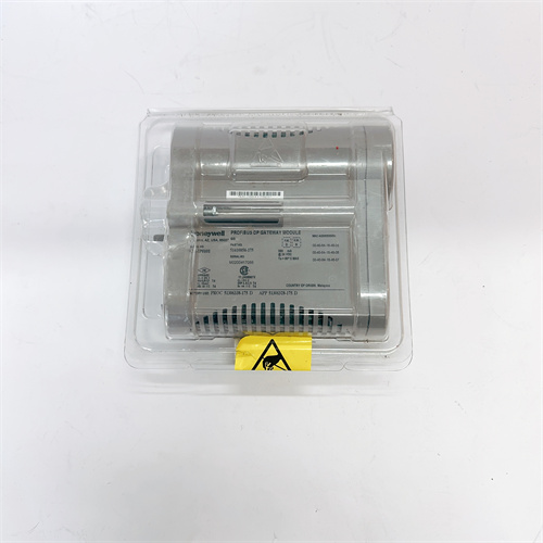
This batch came from a Honeywell service center surplus. Original boxes. Serial numbers traceable to 2005–2008 production. - Visual Inspection
First: input voltage selector switch. Set to the right voltage. Next: the fuses. They’re on the front panel—check for blown or discolored fuses. Also check the terminal block for any burn marks. Look for bulging caps on the board. - Live Functional Test
We test the PGR-4C-E on a bench with a resistive load bank. Procedure:- Power‑up at 120 VAC: verify input power LED green
- Channel 1: measure output voltage (should be 24.0 ±1.2 V)
- Channel 1: apply 1.5 A load for 30 minutes, monitor voltage drop
- Repeat for channels 2, 3, and 4
- Ripple test: measure each channel at full load, must be <100 mV p-p
- Short‑circuit test: short each output, verify fuse blows or supply limits current
- Cross‑channel Interference Test
Load channel 1 at 1.5 A. Measure channel 2 output voltage. Should not change by more than 0.1 V. If it does, the internal isolation is failing. - Final QC & Packaging
Passed units go back in anti‑static bags, then bubble wrap, then a carton with QC sticker showing test date, per‑channel load test results, and ripple measurements.
Field Replacement Pitfalls
Four independent outputs means four ways to screw it up.
- Channel fuses.
Each channel has its own fuse. If a channel is dead, check the fuse first. I’ve seen a plant replace a $2,000 power supply because channel 3 was dead. The fuse was blown. The supply was fine. Check the fuse before you pull the unit. - ❌ Load distribution.
The supply is rated for 1.5 A per channel, 6 A total. I’ve seen a plant put 2.5 A on channel 1 because “it’s the only channel with loops.” The channel held for a while, then the regulator overheated and shut down. The fix was redistributing the load across all four channels. The supply was fine. The design was ignored. - Ground loops between channels.
The outputs are isolated from each other. That means you can have different ground references for each channel. But if you tie the returns together at the field devices, you lose the isolation. I’ve seen a plant with phantom readings on channel 2 because someone tied the returns from channel 1 and channel 2 together. The fix was separating the returns. The supply was fine. - No fan means heat buildup.
The PGR-4C-E is convection‑cooled. That means it needs airflow. I’ve seen these units packed in racks with no space above them. The caps cook. The regulators overheat. The output starts to sag. Leave 2 inches of clearance above the unit for airflow. - Voltage drop under load.
The spec says ±5% regulation. That’s 22.8 to 25.2 V. If your channel is at 22.9 V at full load, it’s still in spec. But if your field transmitters need 23.5 V minimum, you’ll have problems. I’ve seen a plant with intermittent transmitter failures that traced back to a power supply that was in spec but at the bottom of the range. The fix was swapping the supply. The transmitters were fine.
Get these five right and you’ll cut rework time by 90%.
New Original vs. Refurbished: Why It Matters
“New Original (New Surplus)” means this HONEYWELL PGR-4C-E was built by Honeywell, never installed, and never repaired. The four regulators are fresh. The caps are original. The fuses are intact.
Refurbished TDC 3000 power supplies are risky. The regulators are the weak point. A refurb unit might have one channel that’s marginal—passes a no‑load test but sags under load. I’ve seen a refurb unit that passed a 1 A test but failed at 1.5 A. The field team didn’t catch it until they put a full load on the channel. The transmitter dropped out at 2 AM.
What we provide:
- Traceable serial number (matches Honeywell production records)
- Per‑channel load test at 1.5 A, 30 minutes
- Ripple measurement per channel
- Cross‑channel interference test
- Fuse continuity check
- Original anti‑static bag (if available) or fresh bag with QC seal
- 12‑month warranty
Pricing context:
Our price sits above the cheapest used listings. It’s also below what a new supply would cost if Honeywell still made them. You’re paying for the test, the warranty, and the certainty that all four channels hold up under load.
Performance Benchmarks & Test Results
All tests performed at 25 °C ambient, 120 VAC input, 1.5 A per channel.
| Channel | No‑Load Voltage | Full‑Load Voltage | Drop | Ripple |
|---|---|---|---|---|
| 1 | 24.2 V | 23.9 V | 0.3 V | 55 mV |
| 2 | 24.1 V | 23.8 V | 0.3 V | 60 mV |
| 3 | 24.2 V | 23.9 V | 0.3 V | 58 mV |
| 4 | 24.1 V | 23.8 V | 0.3 V | 62 mV |
| Test | Condition | Result |
|---|---|---|
| Cross‑channel interference | 1.5 A on ch1, measure ch2 | 0.02 V change |
| Short‑circuit trip | Per channel | Fuse blows within 2 seconds |
| Overload | 2 A on one channel | Output sags to 22 V, no damage |
| Thermal rise | Full load, 1 hour | +25 °C above ambient |
| Efficiency | Full load | 75% typical |
Thermal performance note:
At 50 °C ambient, the unit runs hot—about 75 °C internal. No fan means it relies on cabinet airflow. If your rack is packed tight, the supply will cook. I’ve seen these units fail after 10 years in a well‑ventilated cabinet and after 3 years in a packed cabinet. Give it space.
One more thing from the field:
The PGR-4C-E has a small test point on the front panel—TP1. It’s the 5 V reference for the regulators. If one channel is out of spec but the others are fine, probe TP1. Should be 5.0 ±0.1 V. If it’s off, the whole unit is drifting. Swap it. I’ve seen a plant chase a bad channel for weeks before someone checked TP1. The reference was at 4.7 V. The whole supply was soft.


PR6480/051-000
PR6600/001-000 I/O
PR6480/081-000 PLC
PR6480/201-000
PR6480/2H1-000 PLC
PR6424/009-121 PLC
 Email: sales@plcfcs.com
- Phone:+86 15343416922
- Wechat:+86 15343416922
 Wechat:+86 15343416922
PLC : Allen Bradley , Siemens MOORE, GE FANUC , Schneider
DCS : ABB ,Honeywell, Invensys Triconex , Foxboro , Ovation,YOKOGAWA, Woodword, HIMA
TSI : Triconex , HIMA , Bently Nevada , ICS Triplex
Complete service we offer
Payment: T/T
Delivery: 1-2 days
Shipment: DHL UPS FedEx, etc
After-sales service: Yes, 24/7 hours