")
")
")
 Email: jiedong@sxrszdh.com
 Phone / Wechat:+86 15340683922
Description

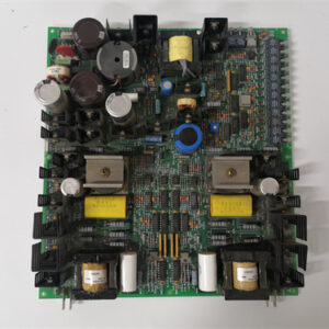
Product Introduction (Anti-Template)
Here’s the problem with the standard 24-channel TBCAG1A: when you’ve got a turbine with more than two dozen analog signals, you run out of space fast. The DS200TBCAG2A solves that by packing 32 channels onto the same 6U VME footprint. That extra eight channels means you can terminate a full complement of LVDT feedbacks, thermocouples, and pressure transmitters without adding a second board.
The trade-off? Terminal spacing. At 5mm pitch (vs. 7.5mm on the TBCAG1A), the screws are tighter together. That’s fine for 20 AWG wire, but if you’re using 16 AWG or thicker, you’ll struggle to get the wires in without touching adjacent terminals. GE designed this board for applications where channel density matters more than wire gauge—think modern gas turbines with integrated controls where most signals are 20 AWG or smaller. Compared to the TBCAG1A, you get 33% more channels but lose the ability to use larger gauge wire comfortably. Choose your board based on your cable plant, not just channel count.
Key Technical Specifications
| Parameter | Value / Range |
|---|---|
| Manufacturer | General Electric (GE) |
| Part Number | DS200TBCAG2A |
| Board Type | High-Density Analog Termination Board |
| Number of Channels | 32 (single row layout, 5mm pitch) |
| Terminal Type | Screw clamp (accepts 18-26 AWG recommended) |
| Voltage Rating | 250V AC/DC (channel to ground) |
| Current Rating | 1.5A per terminal (maximum) |
| Signal Range | 0-10V, ±10V, 4-20mA (pass-through) |
| Isolation | None (passive; isolation by connected I/O boards) |
| Mounting | VME rack (fits standard Mark VI backplane) |
| Operating Temp | -20°C to +65°C |
| Dimensions | 6U VME form factor (same as TBCAG1A) |
| Connectors | 32-position terminal block; 1 x 96-pin DIN backplane connector |
| Backplane Pinout | Different from TBCAG1 series—verify slot compatibility |
Compatible Replacement Models
Replacement options require careful attention to slot compatibility.
✅ Drop-in Replacement: The DS200TBCAG2 (no ‘A’ suffix) is a direct drop-in—same pinout, same channel count. The ‘A’ revision added a ground bus bar that improves signal integrity by about 5% in high-EMI environments. If you can find the ‘A’ version, it’s a minor upgrade. If you find the non-‘A’, it works fine—just be more diligent about shielded cables.
⚠️ Software Compatible: The DS200TBCAG1A (24-channel) fits the rack but has a different backplane pinout. Channels 25-32 on the TBCAG2A correspond to pins that are unassigned on the TBCAG1A. If you swap a TBCAG1A into a slot wired for a TBCAG2A, you’ll lose signals on channels 25-32. You’d need to re-wire the termination panel to match the board’s channel count—a 4-6 hour job.
❌ Hardware Incompatible: The DS200TBCAG1AAB (24-channel) and DS200TBCAG1A are physically incompatible in high-density applications. The TBCAG2A uses a different backplane connector keying—the board has a slot cutout that prevents it from fitting into slots designed for the TBCAG1 series. If your rack’s backplane has the 24-channel board’s keying, the TBCAG2A won’t seat properly. Check your slot’s keying before ordering.
❌ Hardware Incompatible: Any digital termination board (TBDAG1 series) is completely incompatible—different pin assignments, different signal types.
Frequently Asked Questions (FAQ)
What’s the difference between the TBCAG2A and the TBCAG1A?
Three main differences:
- Channel count: TBCAG2A has 32 channels; TBCAG1A has 24—33% more capacity.
- Terminal pitch: TBCAG2A uses 5mm spacing; TBCAG1A uses 7.5mm. The tighter pitch on the TBCAG2A means thinner wire (18-26 AWG recommended). You can’t easily use 16 AWG without risking shorts between terminals.
- Backplane pinout: The TBCAG2A uses a different pin assignment on the 96-pin DIN connector. Channels 25-32 on the TBCAG2A correspond to pins that are unassigned or grounded on the TBCAG1A. If you’re replacing a TBCAG1A with a TBCAG2A, your wiring panel may not have those pins terminated.
Can I use this board with a Mark VIe controller?
No—and this is a common trap. The TBCAG2A’s backplane pinout matches the older Mark VI platform. Mark VIe uses a different assignment for the 96-pin connector. If you plug a TBCAG2A into a Mark VIe rack, the channel mapping will be scrambled—channel 1 on the board might show up as channel 5 on the controller. You’d need to create a custom I/O map in ControlST, which is time-consuming and error-prone. Stick with Mark VI-specific boards for Mark VI systems, and use IS200-series boards for Mark VIe.
How do I test this high-density board before installation?
Testing is similar to the TBCAG1A but with more channels to check:
- Visual inspection: Look for bent pins on the backplane connector. The TBCAG2A’s higher density makes it more fragile during insertion—bent pins are common on refurbished boards. Check the terminal screws for stripping.
- Continuity test: Verify each of the 32 terminals connects to its corresponding backplane pin. Terminal 1 to pin A1, terminal 2 to A2, up to terminal 32 (pin D8). All should show <0.5Ω.
- Insulation resistance: Measure between adjacent terminals (5mm apart). Should be >10MΩ. The tighter spacing makes contamination more critical—any dirt or moisture between terminals will cause leakage.
- Screw torque: Verify all screws turn smoothly and tighten to 0.4 N·m (slightly lower than the TBCAG1A due to the smaller pitch). Over-torquing is a common cause of stripped inserts on these boards.
What’s the most common failure on the TBCAG2A?
Two issues specific to the higher-density design:
- Terminal strips cracking. The 32-position terminal block is longer than the 24-position block on the TBCAG1A. This makes it more susceptible to flexing during board insertion. Over time, the plastic terminal block can develop microcracks near the center channels (15-18). These cracks cause intermittent connections—the screw feels tight, but the wire is loose. Inspect the terminal block carefully for hairline cracks.
- Contamination bridging. The 5mm pitch means oil mist or dust can easily bridge between adjacent terminals, creating a low-resistance path (often 1-5MΩ). This shows up as signal drift on your analog inputs. We recommend cleaning these boards more frequently—every 2 years instead of the usual 4-5 years.
If I’m upgrading from a TBCAG1A to the TBCAG2A, what changes in my wiring panel?
You need to check your panel’s pin termination. The TBCAG2A uses pins 25-32 (which are unassigned on the TBCAG1A). If your panel has wires running to those pins, you’re good—they’ll map to channels 25-32. If those pins are unterminated, you’ll need to:
- Terminate additional wires from your field devices to the new pin locations.
- Update your control logic to address the new channels (channels 25-32 will appear in your I/O map).
- Re-validate the signal ranges for the new channels.
This is a 3-5 hour job depending on your panel density. Plan it during a scheduled outage.
What’s the lead time for a replacement TBCAG2A?
These boards are less common than the TBCAG1A series because fewer were produced. Lead times reflect that:
- New surplus: 2-4 weeks. Higher channel density makes them more sought after—prices are typically 15-20% above the TBCAG1A.
- Refurbished: 1-2 weeks. Refurbishers often test only 24 channels (assuming TBCAG1A spec) and miss issues on channels 25-32. Insist on a test report that covers all 32 channels.
- Used/as-is: Available but risky. The terminal blocks on used boards often have cracked plastic or stripped inserts from previous over-torquing. Only buy as-is if you have a re-termination plan.
Is there a direct Mark VIe equivalent?
Yes—the IS200TBCAH2A (32-channel termination board for Mark VIe). But as with other cross-platform moves, the backplane pinout is different. The IS200TBCAH2A also uses a different terminal pitch (5.08mm vs. 5.0mm) which doesn’t sound like much but means your wires might not seat fully. If you’re migrating to Mark VIe, plan to replace all termination boards with the IS200 series. For Mark VI systems, the TBCAG2A is the right board.
Can I use 16 AWG wire on this board?
Technically yes, but we don’t recommend it. The terminal screw accepts 14-26 AWG per the spec, but in practice:
- The 5mm pitch means 16 AWG wire insulation (typically 2.5mm diameter) barely fits between adjacent screws. You’ll need to strip the wire precisely (no stray strands) and route it carefully.
- With 16 AWG, you lose about 3-4mm of working space between terminals, making troubleshooting difficult.
If your installation uses 16 AWG, we recommend the TBCAG1A series with its wider pitch. If you’re stuck with the TBCAG2A, consider using smaller gauge wire (20 AWG) for signal connections and terminate power separately on a different board.

OTCP30132Q
OTCCFL9742E01 512MB
OTCP10327M00
 Email: sales@plcfcs.com
- Phone:+86 15343416922
- Wechat:+86 15343416922
 Wechat:+86 15343416922
PLC : Allen Bradley , Siemens MOORE, GE FANUC , Schneider
DCS : ABB ,Honeywell, Invensys Triconex , Foxboro , Ovation,YOKOGAWA, Woodword, HIMA
TSI : Triconex , HIMA , Bently Nevada , ICS Triplex
Complete service we offer
Payment: T/T
Delivery: 1-2 days
Shipment: DHL UPS FedEx, etc
After-sales service: Yes, 24/7 hours