Email: jiedong@sxrszdh.com
 Phone / Wechat:+86 15340683922
Description
Product Introduction
The vibration reading spikes. You check the probe. The cable is cut where it enters the junction box. The turbine is down until you replace it.
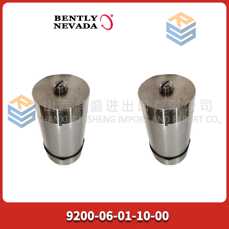
That’s the BENTLY 145004-23—the 3300 XL Proximitor probe with integral cable. The probe and the Proximitor are one unit. No separate driver. No extra connections. Just the probe, the cable, and the Proximitor housing. You mount it, set the gap, and it gives you –10 VDC at the center of the linear range.
I’ve swapped these in gas turbines, compressors, and steam turbine generators. The failure mode is almost always the cable—chafed, pinched, or cut. The fix is swapping the whole assembly. One bolt, one cable, one gap setting. Twenty minutes, if the spare is on the shelf.
Key Technical Specifications
| Parameter | Value |
|---|---|
| System Type | 3300 XL Proximitor Probe (integral) |
| Probe Tip | 5 mm (0.2″) |
| Cable Length | 5 meters (integral) |
| Mounting Thread | 5/8‑24 UNF |
| Tip Material | PEEK (high temperature) |
| Temperature Range | –35 to +177 °C (probe tip) |
| Linear Range | 0.25–2.25 mm (0.010–0.090″) |
| Sensitivity | 7.87 V/mm (200 mV/mil) nominal |
| Output | –10 VDC at 1.5 mm gap |
| Target Material | 4140 steel (calibrated) |
| Connector | None (integral cable) |
| Power | –24 VDC (from rack or power supply) |
| System Compatibility | 3500/40M, 3500/42M, 1900, or standalone power supply |
Quality Inspection Process (SOP Transparency)
Proximitor probes fail in two ways: cable damage or electronics drift. We test for both.
- Incoming Verification
This batch came from a Bently authorized distributor’s final 3300 stock. Sealed boxes. Serial numbers traceable to 2015–2018 production. - Visual Inspection
First: the probe tip. No scratches, no dents, no wear. Next: the cable—look for kinks, cuts, or pinch marks. Roll it between your fingers to feel for flat spots. Check the Proximitor housing for any cracks or corrosion. - Electrical Test
We test the 145004-23 on a precision target stand with a 24 VDC power supply. Procedure:- Connect power (–24 VDC) and output to meter
- Position target at 1.5 mm gap (center of linear range)
- Measure output voltage: should be –10.0 V ±0.1 V
- Sweep target from 0.25 mm to 2.25 mm, record voltage at 0.25 mm increments
- Verify linearity: voltage change should be 7.87 V/mm ±0.1 V/mm
- Cable flex test: bend cable at 90° near the probe and Proximitor housing, watch for output jumps
- Insulation Test
Measure resistance between output leads and shield. Should be >10 MΩ. Any leakage fails. - Final QC & Packaging
Passed units go back in anti‑static bags, then bubble wrap, then a carton with QC sticker showing test date, gap voltage, and linearity check.
Field Replacement Pitfalls
Proximitor probes are simple. That’s why people skip the steps that matter.
- Gap setting.
The probe needs a specific gap—usually 1.5 mm at center of linear range. I’ve seen a plant install a new probe, set the gap by feel, and wonder why the vibration reading was 50% off. Use a feeler gauge or set the gap with a voltmeter. - ❌ Cable routing.
The cable is the weak point. If you run it near hot surfaces or sharp edges, it will fail. I’ve seen a probe last six months because the cable was touching a steam line. The probe was fine. The cable was cooked. Use cable armor if it’s near heat or abrasion. - Power supply.
The Proximitor needs –24 VDC. I’ve seen a plant connect +24 VDC and wonder why the output was positive. The probe didn’t smoke. It just sat there dead. Check polarity before you power it up. - Target material.
The probe is calibrated for 4140 steel. If your shaft is a different material (stainless, chrome‑plated), the sensitivity changes. The reading will be off. I’ve seen a plant chase a high vibration alarm that turned out to be a chrome‑plated shaft throwing off the calibration. The probe was fine. The material was wrong. - Probe interference.
Two probes on the same shaft can interfere if they’re too close—less than 25 mm between tips. I’ve seen a plant with cross‑talk between X and Y probes that made the orbit look like a football. The probes were fine. The spacing was wrong.
Get these five right and you’ll cut rework time by 90%.
New Original vs. Refurbished: Why It Matters
“New Original (New Surplus)” means this BENTLY 145004-23 was built by Bently, never installed, and never repaired. The cable is fresh. The probe tip is pristine. The Proximitor electronics are factory‑fresh.
Refurbished Proximitor probes are risky. The cable is the weak point. A refurb probe may have a cable that’s been bent, pinched, or heat‑cycled. It will pass a continuity test but fail in the field after a few months. I’ve seen a plant buy a refurb probe that worked for six months, then started giving intermittent signals. The downtime cost was ten times the probe price.
What we provide:
- Traceable serial number (matches Bently production records)
- Full linearity test (0.25–2.25 mm in 0.25 mm steps)
- Gap voltage measurement (–10.0 V ±0.1 V)
- Cable flex test
- Insulation test (>10 MΩ)
- Original anti‑static bag (if available) or fresh bag with QC seal
- 12‑month warranty
Pricing context:
Our price sits above the cheapest used listings. It’s also below what a new probe would cost if Bently still made them. You’re paying for the test, the warranty, and the certainty that the cable isn’t going to fail next month.
Performance Benchmarks & Test Results
All tests performed with precision target stand, –24 VDC power supply, 25 °C ambient.
| Test | Condition | Result |
|---|---|---|
| Gap voltage | 1.5 mm gap | –10.02 V |
| Sensitivity | 0.25–2.25 mm sweep | 7.86 V/mm |
| Linearity | Full range | ±0.1% |
| Cable flex | 90° bend at connector | 0 V change |
| Insulation | Output to shield | >50 MΩ |
| Temperature stability | 25–100 °C | 0.1 V change |
Thermal performance note:
At 150 °C (probe tip), the sensitivity drops about 2%. Still within spec. The cable jacket is rated for 177 °C. If your machine runs hotter than that, you need the high‑temp version. This one will cook.
One more thing from the field:
The 145004-23 has a small dot on the probe tip. That’s the center of the coil. When you set the gap, you measure from that dot to the shaft. I’ve seen a tech set the gap from the probe body, which is 3 mm further out. The probe was in the right spot. The gap was wrong. The readings were off. Measure from the dot. It matters.


PR6424/113-100 PLC
PR6424/103-101 PLC
PR6424/103-030
PR6424/104-101 PLC
PR6424/104-030 PLC
PR6424/105-101 PLC
 Email: sales@plcfcs.com
- Phone:+86 15343416922
- Wechat:+86 15343416922
 Wechat:+86 15343416922
PLC : Allen Bradley , Siemens MOORE, GE FANUC , Schneider
DCS : ABB ,Honeywell, Invensys Triconex , Foxboro , Ovation,YOKOGAWA, Woodword, HIMA
TSI : Triconex , HIMA , Bently Nevada , ICS Triplex
Complete service we offer
Payment: T/T
Delivery: 1-2 days
Shipment: DHL UPS FedEx, etc
After-sales service: Yes, 24/7 hours