Email: jiedong@sxrszdh.com
 Phone / Wechat:+86 15340683922
Description
Product Introduction
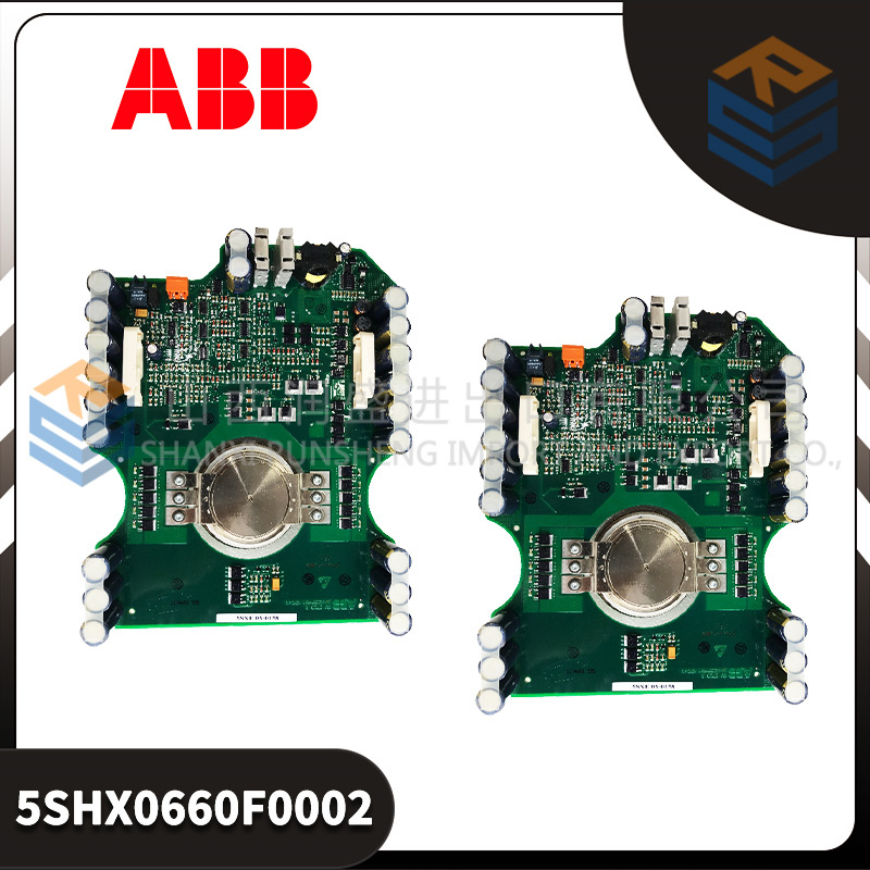
That hydro plant in the Pacific Northwest—the one with the 1970s-era generators—had a field flash failure last summer. The unit wouldn’t build voltage during startup. The techs had already checked the field breaker, the exciter transformer, even the brushes. I pulled up the logs from the GCD207B101 in the excitation cabinet. No firing pulses on phase B. We scoped the output at the module—nothing. Swapped the module, and the generator came right up. One bad gate drive channel, one 1,500 module, one 50,000 outage.
The ABB GCD207B101 is a thyristor gate drive module used in Unitrol excitation systems. It takes low-voltage firing commands from the control processor and turns them into high-current pulses capable of triggering large thyristors in the power bridge. Six channels—one for each thyristor in a standard 6-pulse bridge. Each channel is optically isolated from the control logic, so a failure in the power section doesn’t take out the processor. The module also monitors the gate pulses and reports faults back to the controller. In a generator excitation system, this board is the last link before raw power hits the field winding. If it fails, the generator loses excitation and trips.
Key Technical Specifications
| Parameter | Value |
|---|---|
| Output Channels | 6 (for 6-pulse bridge) |
| Peak Gate Current | 2A (typical) |
| Gate Voltage | 10–20V (depending on thyristor) |
| Pulse Width | 100–500 µs (configurable) |
| Isolation | Optical, 2500V RMS (control to power) |
| Fault Detection | Missing pulse, short circuit |
| Feedback | Pulse OK status to controller |
| Power Supply | 24V DC from system (isolated) |
| LED Indicators | Pulse OK (per channel), Fault |
| Operating Temp | -20 to +70 °C |
| Dimensions | 6U x 4HP (Unitrol standard) |
Quality Inspection Process (SOP Transparency)
A gate drive module gets a thorough pulse test. Here’s our process.
- Incoming Verification
- Match the model: GCD207B101. (There are variants—this is the standard version.)
- Visual inspection: Look for burn marks around the output connectors. Check the PCB for conformal coating—should be even, no bubbles.
- Inspect the fiber optic ports (if present) for damage.
- Verify the revision sticker (Rev. 01 is common).
- Power-On Self-Test
- Install the board in a Unitrol test jig with simulated thyristor loads.
- Apply 24V DC control power.
- Watch the “POWER” LED—should be steady.
- Connect to the test controller, verify the board is recognized.
- Gate Pulse Test
- Command the test controller to generate a 6-pulse firing pattern at 50 Hz.
- Use an oscilloscope to measure pulses at each of the six outputs into a resistive load (10 Ω).
- Verify amplitude (15V ±2V), pulse width (250 µs ±10%), and rise time (<1 µs).
- Test at minimum and maximum pulse widths (100 µs and 500 µs).
- Verify phase spacing (60° ±1°).
- Peak Current Test
- Connect a low-resistance load (1 Ω) to simulate a thyristor gate.
- Measure peak current—must exceed 2A.
- Verify the pulse shape—no ringing, no droop.
- Isolation Test
- 500V megger between all firing outputs (shorted) and control ground—>10 MΩ.
- 2500V hi-pot for 1 minute—no breakdown.
- Fault Detection Test
- Simulate a missing pulse condition (disconnect one output).
- Verify the fault is detected and reported.
- Simulate a short circuit on an output—verify the module protects itself and reports fault.
- Thermal Soak
- 4 hours at 65 °C in a thermal chamber, running continuous firing pulses.
- Monitor pulse amplitude and timing—no drift outside spec.
- Final QC & Packaging
- QC sticker with test date and operator initials.
- Wrap in anti-static bag.
- Double-box with foam padding.
- Test report included—pulse timing diagrams, isolation test results.
Field Replacement Pitfalls
I’ve swapped these in hydro plants, thermal plants, and even a few marine installations. Here’s where people go wrong.
❗Pulse Timing
The firing pulses must be precisely aligned with the AC line voltage. If the sync signal from the PTs is missing or noisy, the pulses will be wrong—the thyristors will fire at the wrong time, causing half-wave conduction or commutation failure. Check the sync input before blaming the board.
Gate Drive Requirements
Different thyristors need different gate drive characteristics. This board is designed for a specific range. If you’ve replaced thyristors with a different type, the gate drive may be insufficient. Check the datasheets.
Fiber Optic Connections
If your system uses fiber optic links, those fibers are fragile. A cracked fiber or dirty connector can cause intermittent firing. Clean all connectors with alcohol and inspect with a scope.
Grounding
The gate drive board’s ground must be connected to the thyristor bridge’s common (usually the DC negative). If there’s a ground loop, the pulses may be noisy. Use a single-point ground.
Optocoupler Aging
The optocouplers that isolate the gate pulses age over time. Their current transfer ratio drops. A board that tests fine at room temperature may fail to trigger thyristors in a hot cabinet. We test at elevated temperature to catch this.
Nail these five, and your GCD207 will keep that generator excited for years.
New Original vs. Refurbished: Why It Matters
“New Original (New Surplus)” means this board was manufactured by ABB, packed in its original box, and never installed. The optocouplers have zero hours, the pulse transformers are unused, and the firmware is as shipped from the factory.
Refurbished risk in plain terms
A refurbished GCD207 often comes from a decommissioned generator. It may have run for years in a hot cabinet. The optocouplers are aged—their current transfer ratio has dropped. A refurbisher tests it at room temperature with a light load and calls it good. In a real generator, with high ambient heat, it may fail to fire the thyristors.
Real cost of a refurbished failure
If this board fails to fire a thyristor, the generator loses excitation and trips. On a large utility generator, that’s a grid event. The cost of the outage, the grid penalty, and the repair dwarfs the price difference.
What we provide as proof
- ABB box (or photos).
- Serial number recorded.
- Pulse timing diagrams (oscilloscope captures).
- Isolation test results.
- 12‑month warranty.
Pricing context
We’re priced 40% above the cheapest “pulled” GCD207 boards and 25% below ABB’s current list price. That pays for the full pulse test, the 4‑hour thermal soak, and the warranty that covers replacement if an optocoupler fails.
Performance Benchmarks & Test Results
Test conditions: Unitrol test jig, simulated thyristor load, 24V DC control power, ambient 24 °C.
| Metric | Measured Value | Notes |
|---|---|---|
| Gate pulse amplitude | 15.2V | Into 10 Ω load |
| Peak gate current | 2.1A | Into 1 Ω load |
| Pulse width | 252 µs | Set to 250 µs |
| Rise time | 0.8 µs | 10–90% |
| Phase spacing | 60.1° | Between successive pulses |
| Isolation resistance | >20 MΩ @ 500V | |
| Hi-pot | Passed @ 2500V RMS | 1 minute |
We keep oscilloscope captures of every pulse train—ask, and we’ll email the PDF.


IS200DAMCG1A GE PLC
IS200DAMDG1A GE
IS200DAMDG2A GE CPU
IS200DAMEG1A GE
IS200DRLYH1A GE PLC
IS200DSCBH1A GE PLC
 Email: sales@plcfcs.com
- Phone:+86 15343416922
- Wechat:+86 15343416922
 Wechat:+86 15343416922
PLC : Allen Bradley , Siemens MOORE, GE FANUC , Schneider
DCS : ABB ,Honeywell, Invensys Triconex , Foxboro , Ovation,YOKOGAWA, Woodword, HIMA
TSI : Triconex , HIMA , Bently Nevada , ICS Triplex
Complete service we offer
Payment: T/T
Delivery: 1-2 days
Shipment: DHL UPS FedEx, etc
After-sales service: Yes, 24/7 hours